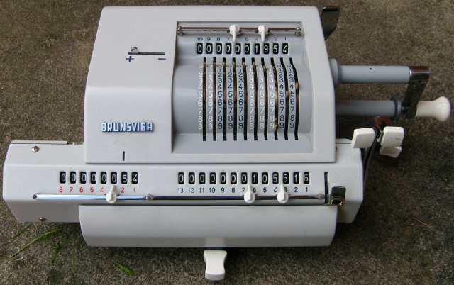
A Brunsviga having just completed the multiplication 1954 * 54 = 105516.
This one was made, in Spain, by Olympia Werke AG of Wilhelmshaven, in the late 1960s probably.
The parts are shown below:
The body of the calculator is part A, it is a heavy casting and has rubber feet to resist sliding on the desk. The part B is the carriage which can be moved left and right using the toggle bar D or the front lever H. The addend is placed on the display J using the levers K. Once J has been set, each clockwise rotation of the handle C adds the number at J into the accumulator register at M, and each anticlockwise rotation subtracts it. When the carriage is at its most leftwards position, the addend is added into the units column of the accumulator. As the carriage is moved to the right, the addend is added into higher positions. In the picture, the carriage is one space to the right (see tick mark above the N register), so each clockwise revolution of the handle will actually add ten times the addend.
To get to the state shown in the picture, the addend J was set to 1954, the carriage placed fully to the left, and the handle turned 4 times clockwise, resulting in 4*1954 = 7816 in the accumulator. Then the carriage was moved one place to the right and the handle turned 5 times clockwise, resulting in 7816 + 5*10*1954 = 105516. The counter register N records the number of turns allowing for the position of the carriage, so it counts in tens when the carriage is one place to the right.
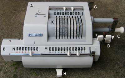
The other controls are: E pulls forward to clear the counter register N, F pulls forward to clear the accumulator register M, G pulls forward to clear the addend register J, L determines whether counter register N counts up or down for clockwise rotation of the handle. Lever I is interesting. It is used to chain calculations. If register J is cleared, the carriage is aligned full left and lever I is pushed up, then clearing the accumulator with F will transfer the value that was in the accumulator into register J. It can be a bit stiff if there are a lot of digits to transfer, but it works and saves having to write down intermediate results.
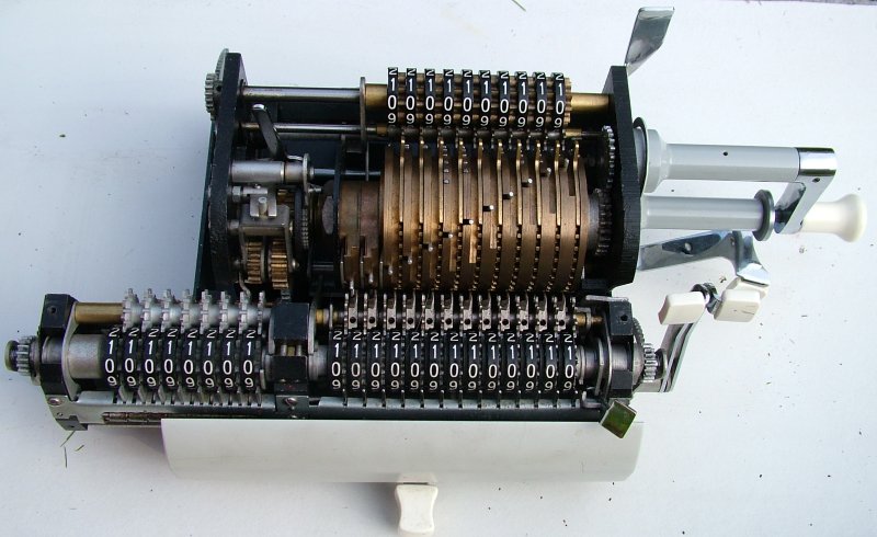
This is what it looks like with the covers off:
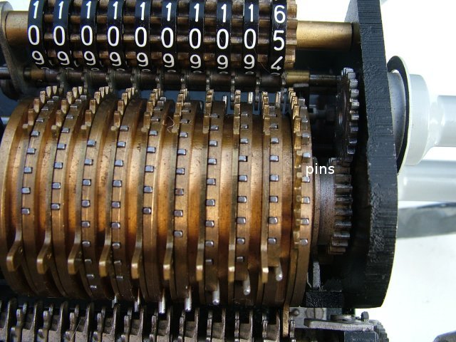
In the next picture the number 5 has been set on the addend levers and the handle turned part way. On the right-hand side of the drum you can see that five of the nine pins in the right-hand column are now standing out from the drum. As these pins pass the accumulator register they will advance the right-hand wheel by five teeth and thus add five to the right-hand column.
The levers near the bottom of the picture are the setting levers K. The other teeth that are visible are used to drive the addend display register at the top and for transferring numbers back from the accumulator.
In the next picture the handle has been turned a bit further and the pins are engaged with the gear of the right-hand most digit and are pushing it round, so far it has counted two of them, with three to go.
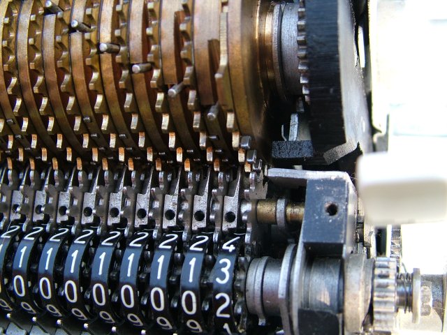
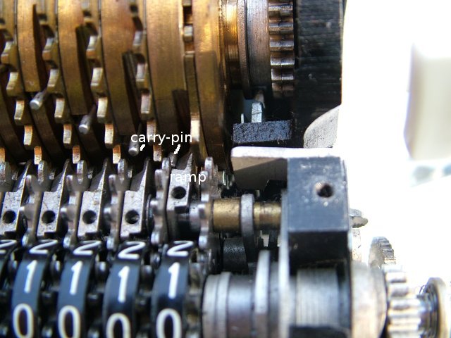
Now this is a little later. The handle has now made one complete turn to put 5 into the accumulator and another part turn, which has brought the right-hand wheel another five steps, back to zero. Now a carry into the next column is required. This is done by the ramp which has been pushed forward as the wheel went from showing 9 to showing zero. Each column has a spring loaded carry pin, two of which are labelled. Normally they pass between the wheels of the accumulator, but when a ramp has been pushed forward they are diverted to the left and forced to mesh with the accumulator wheel of the next digit to the left. In the picture the right-hand most pin can be seen just about to advance the tens digit.
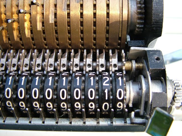
And finally after completing the second turn of the handle the accumulator is showing 10 as expected, and the ramp has dropped back into line.
The carry pins are spread out around the drum so that carries propagate in sequence from right to left. This can be quite stiff when the register is changing from 9999999999999 to 0000000000000. There are actually two sets of carry pins, the other set being for subtraction. These operate on another part of the drum, as they still have to work after the pins have done their work, and from right to left, with the drum rotating the opposite way. So the drum has three zones: subtraction carry; pin add/subtract; addition carry. In the general picture of the insides above, the subtraction carry zone is visible, the pin zone is just starting at the top and the addition carry is round the back. Remember that there is a reversing gear on the handle, so for addition, clockwise rotation of the handle, the drum rotates top towards you.
 2008-10-18 .. 2008-10-18
(+44 7010 700642)
2008-10-18 .. 2008-10-18
(+44 7010 700642)